Vehicles without AVS (Adaptive Variable Suspension System)
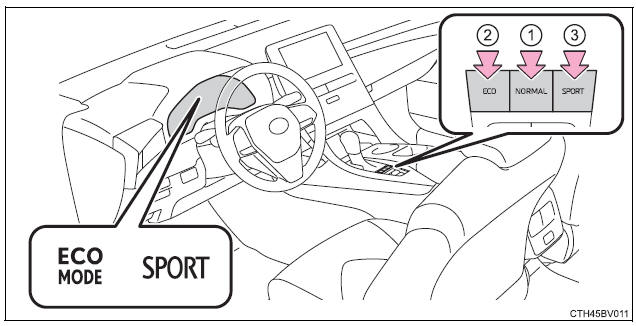
While in Eco drive mode or Sport mode, press the "NORMAL" switch to change the driving mode to normal mode.
When the "ECO" switch is pressed, the "ECO MODE" indicator comes on in the multi-information display.
When the "SPORT" switch is pressed, the "SPORT" indicator comes on in the multi-information display.
Vehicles with AVS (Adaptive Variable Suspension System)
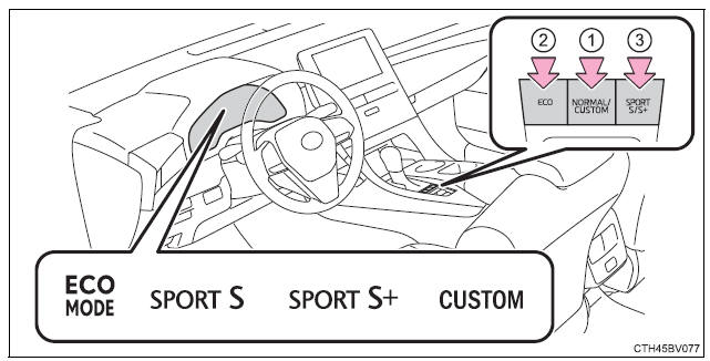
While in Eco drive mode, Sport mode or Custom mode press the "NORMAL/ CUSTOM" switch to change the driving mode to normal mode.
Custom mode settings can only be changed on the drive mode customization display of the audio system screen.
(Displaying the drive mode customization display)
When the "NORMAL/CUSTOM" switch is pressed, the "CUSTOM" indicator
comes on in the multi-information display.
| Function | Setting |
|
Powertrain |
Normal |
| Power | |
| Eco | |
| Chassis | Normal |
| Sport | |
| Air conditioning system | Normal |
| Eco |
When the "ECO" switch is pressed, the "ECO MODE" indicator comes on in the multi-information display.
When not in SPORT S mode, if the "SPORT S/S+" switch is pressed, the "SPORT S" indicator will come on in the multi-information display.
When in SPORT S mode, if the "SPORT S/S+" switch is pressed, the "SPORT S+" indicator will come on in the multi-information display.
â– Operation of the air conditioning system in Eco drive mode Eco drive mode controls the heating/cooling operations and fan speed of the air conditioning system to enhance fuel efficiency. To improve air conditioning performance, adjust the fan speed or turn off Eco drive mode.
â– Automatic deactivation of sport mode and custom mode If the engine switch is turned off after driving in sport mode or custom mode, the drive mode will be changed to normal mode.
Toyota Avalon (XX50) 2019-2022 Service & Repair Manual > Suspension Control: Front Acceleration Sensor
Components COMPONENTS ILLUSTRATION *A for LH Side - - *1 COWL SIDE TRIM SUB-ASSEMBLY LH *2 FRONT DOOR SCUFF PLATE LH *3 NO. 1 INSTRUMENT PANEL UNDER COVER SUB-ASSEMBLY - - ILLUSTRATION *A for RH Side - - *1 COWL SIDE TRIM SUB-ASSEMBLY RH *2 FRONT DOOR OPENING TRIM WEATHERSTRIP RH *3 FRONT DOOR SCUFF ...


